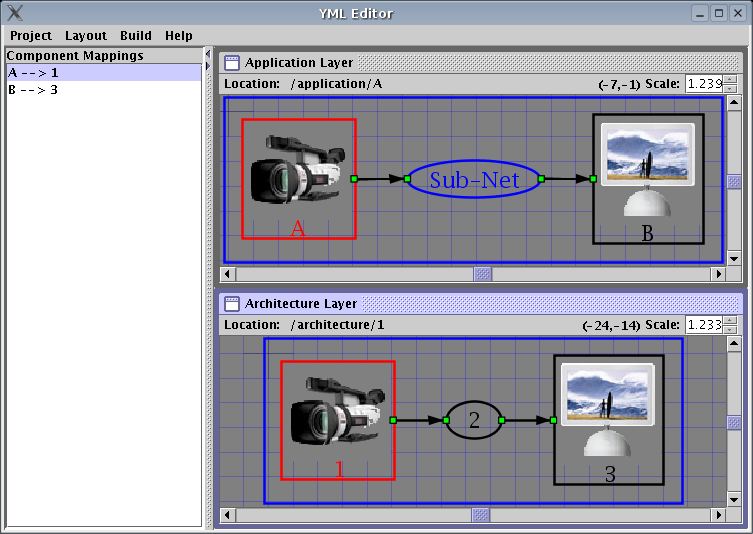
Initially there are no mappings. A screen shot of the mapping editor is shown below:
To create a new mapping right click on the Application Mapping list and select Create New Map from the popup menu. If there are mappable nodes or channels this will open a dialog which displays possible mappings. Select the source and destination from the drop down menus. An application node or channel can only be mapped on to one architecture template. However, more than one application node or channel can be mapped on to the same architecture template.
The mapping editors will only show mappings between the currently displayed networks. In order to map nodes in sub-networks or parent networks you must first open these networks by double clicking or selecting the Up option from the popup menu.
Deleting application mappings will also delete the corresponding virtual layer nodes. This loses any changes made directly to the virtual layer. For this reasons is recommended to make changes to architecture templates when at all possible. Other wise save a copy of the virtual layer before making any mapping changes. This feature, however, makes it much easier to change application mappings and rerun the simulation reflecting these changes because the virtual layer is automatically corrected by the Virtual Layer Generator.
For the most part the YMLEditor keeps mappings synchronized with name changes and deletions in the graph editors. However the current implementation of the YMLEditor does not update virtual and template mappings when they are not active, i.e. loaded into the graph editor. This means that name changes and deletions in the architecture layer may invalidate virtual and template layer mappings. In such case these invalid mappings must be deleted and recreated. This is a known bug in the YMLEditor and will be corrected in a future release.
| Note |
|---|
|
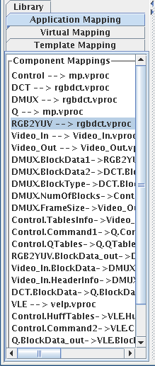
Virtual and template layer mappings are stored in mapping
YML properties. In the virtual layer there is only one mapping
property per node. Architecture templates may contain more than
one mapping. Mappings are differentiated by a name. This name is
stored in the property value attribute. This name is used
to identify the matching template property. This is
demonstrated in the example below.
  <property name="template" value="A">
    . . .
  </property>
  <property name="template" value="B">
    . . .
  </property>
  <property name="mapping" value="A">
    . . .
  </property>
  <property name="mapping" value="B">
    . . .
  </property>
In the example there are two templates A and B with corresponding mappings. |